Summary
This article provides calculation methods for correlating design, flow rate and pressure loss as a fluid passes through a nozzle or orifice. Nozzles and orifices are often used to deliberately reduce pressure, restrict flow or to measure flow rate.
Definitions
| : | Diameter | |
| : | Area | |
| : | Discharge coefficient | |
| : | Gravitational acceleration | |
| : | Fluid head | |
| : | Change in fluid head | |
| : | Ratio of specific heats ( ) | |
| : | Pressure | |
| : | Differential pressure ( ) | |
| : | Expansion coefficient ( for incompressible flow) | |
| : | Elevation | |
| : | Ratio of pipe diameter to orifice diameter ( ) | |
| : | Mass density |
Subscripts:
| : | Upstream of orifice or nozzle | |
| : | Downstream of orifice or nozzle | |
| : | Compressible fluid | |
| : | Incompressible fluid | |
| : | Orifice or nozzle | |
| : | Static pressure |
Introduction
In the case of a simple concentric restriction orifice the fluid is accelerated as it passes through the orifice, reaching the maximum velocity a short distance downstream of the orifice itself (the Vena Contracta). The increase in velocity comes at the expense of fluid pressure resulting in low pressures in the Vena Contracta. In extreme cases this may lead to cavitation when the local pressure is less than the vapour pressure of a liquid.
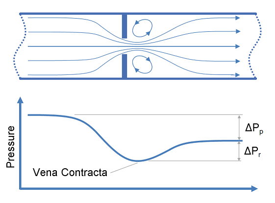
Downstream of the Vena Contracta in the recovery zone, the fluid decelerates converting excess kinetic energy into pressure as it slows. When the fluid has decelerated and returned to the normal bulk flow pattern the final downstream pressure has been reached.
The discharge coefficient characterises the relationship between flow rate and pressure loss based on the geometry of a nozzle or orifice. You can find typical values in our article on discharge coefficients for nozzles and orifices.
Calculations
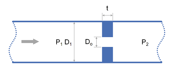
The relationships for flow rate, pressure loss and head loss through orifices and nozzles are presented in the subsequent section. These relationships all utilise the parameter , the ratio of orifice to pipe diameter which is defined as:
Where the point downstream of the orifice is sufficiently far away that the fluid has returned to normal full pipe velocity profile.
Horizontal Orifices and Nozzles
For orifices and nozzles installed in horizontal pipework where it can be assumed that there is no elevation change, head loss and flow rate may be calculated as follows:
| Property | Formula |
|---|---|
| Flow rate (in terms of ) | |
| Flow rate (in terms of ) | |
| Pressure loss | |
| Head Loss |
Vertical Orifices and Nozzles
For orifices and nozzles installed in vertical piping, with elevation change , the following head loss and flow rate equations may be used:
| Property | Formula |
|---|---|
| Flow rate (in terms of ) | |
| Flow rate (in terms of ) | |
| Pressure loss | |
| Head Loss |
Expansion Coefficient
The expansion coefficient takes account of the difference between the discharge coefficient for compressible and incompressible flows. It is defined as:
The expansion factor is typically determined empirically and can be calculated using one of the formulas below.
For incompressible fluids:
American Gas Association method as described in AGA 3.1:
International Standards Organistion method as described in ISO 5167-2: