Summary
Fittings such as elbows, tees and valves represent a significant component of the pressure loss in most pipe systems. This article details the calculation of pressure losses through pipe fittings and some minor equipment using the equivalent length method. The strength of the equivalent length method is that it is very simple to calculate. The weakness of the equivalent length method is that it is not as accurate as other methods unless very detailed tabulated data is available.
Definitions
| : | Internal diameter of pipe | |
| : | Equivalent length of pipe | |
| : | Ratio of elbow radius to pipe diameter |
Introduction
The equivalent length method (L/D ratio) allows the user to describe the pressure drop through a fitting as a length of pipe. In theory the pressure drop through the fitting is equivalent to the pressure lost through a certain length of piping at that corresponding flow rate.
The most accurate way to use this method is when tabulated data is available for fittings at the given size, roughness and Reynolds Number for which the pressure drop is unknown. When using an equivalent length that was determined from a fitting of a different size the method relies on the assumption that as pipe size changes the fitting size retains the same relative proportions. This is rarely the case however, and as such some error is introduced in the pressure drop that results. Similarly the roughness and Reynolds Number are likely to be different from the conditions under which the fitting was characterised and error will be introduced.
Typically as the fittings size increase the flow coefficient (L/D ratio) decreases, thus at pipe sizes larger than those at which the fittings equivalent length was determined the pressure drop will be over-estimated. At smaller pipe sizes than those at which the equivalent length was estimated the pressure drop will be under-estimated.
The advantage of the equivalent length method is that it is very simple to calculate. All pipe runs and fittings can be summed up to make one total length, and the pressure loss calculated from this length.
There are several alternative methods for calculating pressure loss from fittings, such as:
For a discussion of which method is most appropriate see this summary of methods for estimating pressure loss from fittings.
Values for the Equivalent Length of Pipe for Various Fittings
Typical values for the equivalent length of pipe for various fittings are shown in the table below.
After summing these equivalent lengths as appropriate for your hydraulic system, you may simply calculate the pressure drop for the resulting length of pipe.
| Category | Fitting | Types | |
|---|---|---|---|
| Elbow | 90° Curved, Threaded | Standard Radius (R/D = 1) | 30 |
| Elbow | 90° Curved, Threaded | Long Radius (R/D = 1.5) | 16 |
| Elbow | 90° Curved, Flanged/Welded | Standard Radius (R/D = 1) | 20 |
| Elbow | 90° Curved, Flanged/Welded | Long Radius (R/D = 2) | 17 |
| Elbow | 90° Curved, Flanged/Welded | Long Radius (R/D = 4) | 14 |
| Elbow | 90° Curved, Flanged/Welded | Long Radius (R/D = 6) | 12 |
| Elbow | 90° Mitered | 1 weld (90°) | 60 |
| Elbow | 90° Mitered | 2 welds (45°) | 15 |
| Elbow | 90° Mitered | 3 welds (30°) | 8 |
| Elbow | 45° Curved, Threaded | Standard Radius (R/D = 1) | 16 |
| Elbow | 45° Curved, Threaded | Long Radius (R/D = 1.5) | |
| Elbow | 45° Mitered | 1 weld 45° | 15 |
| Elbow | 45° Mitered | 2 welds 22.5° | 6 |
| Elbow | 180° Bend | Threaded, close-return (R/D = 1) | 50 |
| Elbow | 180° Bend | Flanged (R/D = 1) | |
| Elbow | 180° Bend | All types (R/D = 1.5) | |
| Tee | Through-branch as an Elbow | Threaded (r/D = 1) | 60 |
| Tee | Through-branch as an Elbow | Threaded (r/D = 1.5) | |
| Tee | Through-branch as an Elbow | Flanged (r/D = 1) | 20 |
| Tee | Through-branch as an Elbow | Stub-in branch | |
| Tee | Run-through | Threaded (r/D = 1) | 20 |
| Tee | Run-through | Flanged (r/D = 1) | |
| Tee | Run-through | Stub-in branch | |
| Valve | Angle valve | 45°, full line size, | 55 |
| Valve | Angle valve | 90° full line size, | 150 |
| Valve | Globe valve | Standard, | 340 |
| Valve | Plug valve | Branch flow | 90 |
| Valve | Plug valve | Straight through | 18 |
| Valve | Plug valve | Three-way (flow through) | 30 |
| Valve | Gate valve | Standard, | 8 |
| Valve | Ball valve | Standard, | 3 |
| Valve | Diaphragm | Dam type | |
| Valve | Swing check valve | 100 | |
| Valve | Lift check valve | 600 | |
| Tee | Hose Coupling | Simple, Full Bore | 5 |
Example Calculation of Pressure Loss using Equivalent Lengths
This example demonstrates how to use the equivalent length method to calculate the pressure loss through simple pipe and fitting arrangement. The example uses water in system of standard weight carbon steel pipe. Note that for this example we consider a flat system, with no elevation changes.
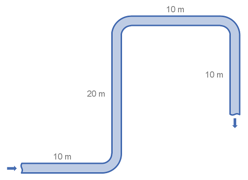
System details
| Item | Value |
|---|---|
| Pipe Size | DN100 (4") |
| Pipe Diameter | 102.3 mm |
| Pipe Length | 50 m |
| Fittings | 3 × 90° long radius (R/D = 2) elbows |
| Fluid Velocity | 3 m/s |
| Fluid Density | 1000 kg/m^{3} |
| Friction Factor | 0.018 |
Calculation
Using the table of fittings and equivalent lengths above we find that the equivalent length for the 90° elbow is 17 pipe diameters.
Taking the pipe length and number of elbows we calculated the equivalent length of the pipe work for pressure loss purposes.
Using the equation for pressure loss in pipe: