Summary
Fittings such as elbows, tees, valves and reducers represent a significant component of the pressure loss in most pipe systems. This article details the calculation of pressure losses through pipe fittings and some minor equipment using the K-value method, also known as the Resistance Coefficient, Velocity Head, Excess Head or Crane method.
Definitions
| : | Internal diameter of pipe | |
| : | Pipe friction factor | |
| : | Acceleration due to gravity | |
| : | Head loss | |
| : | Resistance Coefficient | |
| : | Length as indicated | |
| : | Average velocity |
Introduction
The K-value, Resistance Coefficient, Velocity Head, Excess Head or Crane method allows the user to characterise the pressure loss through fittings in a pipe. The K-value represents the multiple of velocity heads that will be lost by fluid passing through the fitting.
It is more accurate than the Equivalent Length method, as it can be characterised against varying flow conditions (i.e. Reynold Number). However it is less accurate than other methods as it does not take into account the varying geometries of fittings at different sizes. For example a DN 50 (2") long radius 90° elbow is not geometrically similar to a DN 150 (6") long radius 90° elbow, thus the K-value is inaccurate at sizes other than that of the fitting used to determine the K-value. These K-values also generally assume fully developed turbulent flow, and thus are inaccurate at low Reynolds Numbers.
There are several other methods for calculating pressure loss from fittings, such as:
K-Value Method and Typical Values
The Velocity head method is named as such because it represents the pressure loss through a fitting as the equivalent number of “velocity heads”. It is in some ways similar to the equivalent length method, and the two may be equated by the formula below:
Formula for Calculating Head Loss from K Values
where is the equivalent length.
Values of K for Various Fitting Types
There are many tabulations of K-values, as well as methods for calculating K-values. Below is table of typical K-values for various fitting types.
| Category | Fitting | Types | K |
|---|---|---|---|
| Elbow | 45° | Standard (R/D = 1) | 0.35 |
| Elbow | 45° | Long Radius (R/D = 1.5) | 0.2 |
| Elbow | 90° Curved | Standard (R/D = 1) | 0.75 |
| Elbow | 90° Curved | Long Radius (R/D = 1.5) | 0.45 |
| Elbow | 90° Square or Mitred | 1.3 | |
| Elbow | 180° Bend | Close Return | 1.5 |
| Tee | Run Through | Branch Blanked | 0.4 |
| Tee | Tee as Elbow | Entering in run | 1 |
| Tee | Tee as Elbow | Entering in branch | 1 |
| Tee | Tee Branching Flow | 1 | |
| Joiner | Coupling | All | 0.04 |
| Joiner | Union | All | 0.04 |
| Valve | Gate valve | Fully Open | 0.17 |
| Valve | Gate valve | 3/4 Open | 0.9 |
| Valve | Gate valve | 1/2 Open | 4.5 |
| Valve | Gate valve | 1/4 Open | 24 |
| Valve | Diaphragm valve | Fully Open | 2.3 |
| Valve | Diaphragm valve | 3/4 Open | 2.6 |
| Valve | Diaphragm valve | 1/2 Open | 4.3 |
| Valve | Diaphragm valve | 1/4 Open | 21 |
| Valve | Globe valve, Bevel Seat | Fully Open | 6 |
| Valve | Globe valve, Bevel Seat | 1/2 Open | 9.5 |
| Valve | Globe Valve, Composition Seat | Fully Open | 6 |
| Valve | Globe Valve, Composition Seat | 1/2 Open | 8.5 |
| Valve | Plug disk valve | Fully Open | 9 |
| Valve | Plug disk valve | 3/4 Open | 13 |
| Valve | Plug disk valve | 1/2 Open | 36 |
| Valve | Plug disk valve | 1/4 Open | 112 |
| Valve | Angle valve | Fully Open | 2 |
| Valve | Y valve or blowoff valve | Fully Open | 3 |
| Valve | Plug cock | 0.05 | |
| Valve | Plug cock | 0.29 | |
| Valve | Plug cock | 1.56 | |
| Valve | Plug cock | 17.3 | |
| Valve | Plug cock | 206 | |
| Valve | Butterfly valve | 0.24 | |
| Valve | Butterfly valve | 0.52 | |
| Valve | Butterfly valve | 1.54 | |
| Valve | Butterfly valve | 10.8 | |
| Valve | Butterfly valve | 118 | |
| Valve | Check valve | Swing | 2 |
| Valve | Check valve | Disk | 10 |
| Valve | Check valve | Ball | 70 |
| Valve | Foot valve | 15 | |
| Meter | Water meter | Disk | 7 |
| Meter | Water meter | Piston | 15 |
| Meter | Water meter | Rotary (star-shaped disk) | 10 |
| Meter | Water meter | Turbine-wheel | 6 |
Example Calculation of Pressure Loss using K-values
Overview
This example demonstrates how to use the excess head method to calculate the head loss through simple pipe and fitting arrangement. The example uses water in system of standard weight carbon steel pipe. Note that for this example we consider a flat system, with no elevation changes.
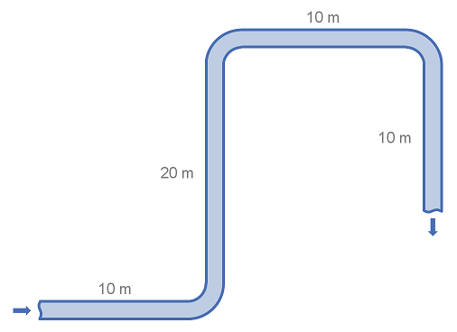
System details
| Item | Value |
|---|---|
| Pipe Size | DN100 (4") |
| Pipe Diameter | 102.3 mm |
| Pipe Length | 50 m |
| Fittings | 3 × 90° long radius (R/D = 1.5) elbows |
| Fluid Velocity | 3 m/s |
| Fluid Density | 1000 kg/m^{3} |
| Friction Factor | 0.018 |
| Gravitational Acceleration | 9.81 m/s^{2} |
Calculation
Using the table of fittings and K-values above we find that the K-value for the 90° elbow is 0.45. With this we can calculate the head loss for a single elbow.
Using the equation for head loss in pipe, we can calculate the loss through the straight piping:
The total head loss for the system is the addition of the head loss from the pipe and the fittings.
In the above example we first calculated the head loss for a single fitting and then multiplied by the number of fittings. It is also correct to add or multiply the K-values of fittings and then convert to a pressure or head loss. This is useful when there are many fittings of several types.