Fluid Flow
Fittings such as elbows, tees, valves and reducers represent a significant component of the pressure loss in most pipe systems. This article details the calculation of pressure losses through pipe fittings and some minor equipment using the K-value method, also known as the Resistance Coefficient, Velocity Head, Excess Head or Crane method.
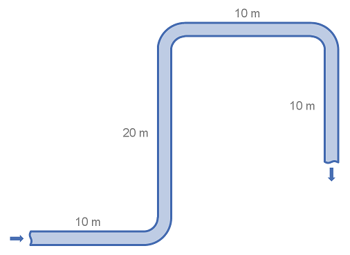
Fittings such as elbows, tees and valves represent a significant component of the pressure loss in most pipe systems. This article details the calculation of pressure losses through pipe fittings and some minor equipment using the equivalent length method. The strength of the equivalent length method is that it is very simple to calculate. The weakness of the equivalent length method is that it is not as accurate as other methods unless very detailed tabulated data is available.
This article describes the method of calculating the velocity head of flowing fluid. The velocity head uses units of length as a measure of the kinetic energy of the flowing fluid.
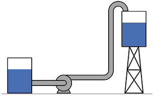
This article presents the method to convert between pressure and head for several common unit sets. Head relates the pressure of a fluid to the height of a column of that fluid which would produce an equivalent static pressure at its base. It is particularly useful for the specification of pumps as it provides a measure of pressure as it is independent of fluid density.
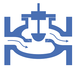
There are several common ways to express the losses caused by pipe fittings and equipment. Depending on the calculation programs or methods available and engineer may require to convert between one form or another. This article details the equations required to convert between the resistance coefficient and flow coefficient methods (K, and ).
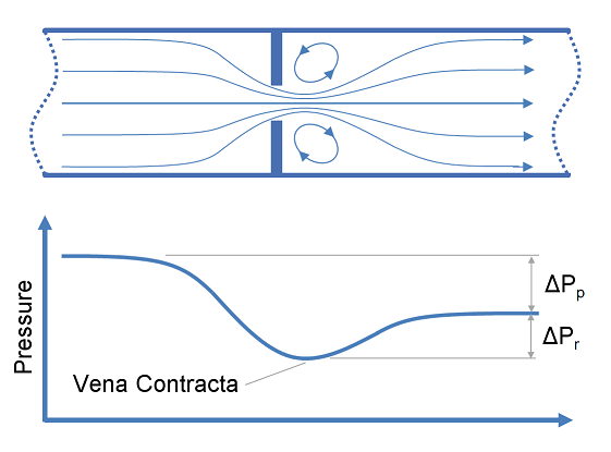
Restriction orifices and control valves are commonly used for pressure reduction and measurement of flow rates, however for a liquid system, excessive pressure drop across these items of equipment may result in cavitation. This article describes methods of predicting cavitation across restriction orifices and valves and proposes designs which may be used to avoid cavitation.
Definitions
| : | Cavitation Index (often σ) | |
| : | Upstream Pressure (absolute) | |
| : | Downstream Pressure (absolute) | |
| : | Fluid Vapour Pressure | |
| : | Permanent Pressure Loss | |
| : | Recoverable Pressure Loss |
Introduction
Cavitation occurs in liquid systems and is the result of rapid formation and collapse of vapour bubbles in the liquid. Cavitation must be avoided or controlled as the collapse of vapour bubbles releases significant energy at the location of the bubble collapse. The consequences of this energy release are typically loud noise and pitting damage to contact surfaces, which over time may result in significant damage to or failure of equipment such as pumps or valves.
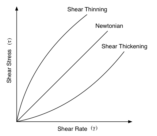
Viscosity is a measure of a fluids propensity to flow. There are two kinds of viscosity commonly reported, kinematic and dynamic. Dynamic viscosity is the relationship between the shear stress and the shear rate in a fluid. The Kinematic viscosity is the relationship between viscous and inertial forces in a fluid. Most common fluids are Newtonian fluids and their viscosity is constant with shear stress and shear rate. Non-Newtonian fluids are less common.
Fittings such as elbows, tees, valves and reducers represent a significant component of the pressure loss in most pipe systems. This article discusses the differences between several popular methods for determining the pressure loss through fittings. The methods discussed for fittings are: the equivalent length method, the K method (velocity head method or resistance coefficient method), the two-K method and the three-K method. In this article we also discuss method for calculating pressure loss through pipe size changes as well as control valves.

The pump affinity laws allow the prediction of centrifugal pump performance given changes to the speed of the pump or the diameter of impeller. This article presents the pump affinity laws for reference.
Power is consumed by a pump, fan or compressor in order to move and increase the pressure of a fluid. The power requirement of the pump depends on a number of factors including the pump and motor efficiency, the differential pressure and the fluid density, viscosity and flow rate. This article provides relationships to determine the required pump power.
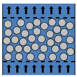
The packed bed Reynolds number is dimensionless and describes the ratio of inertial to viscous forces for fluid flow through a packed bed. It may be used to calculate the pressure drop though a packed bed via the Ergun equation or identify the boundaries of flow regimes (laminar, transitional and turbulent) in a packed bed. This article will show you how to calculate and interpret the packed bed Reynolds number.
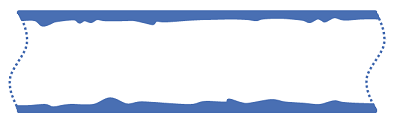
Absolute roughness is a measure of the surface roughness of a material which a fluid may flow over. Absolute roughness is important when calculating pressure drop particularly in the turbulent flow regime. This article provides some typical absolute roughness values for common conduit materials.
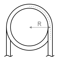
In order to determine the pressure drop in a pipe or coil the friction factor must first be calculated. This article presents the equations which may be used to determine the friction factor in coils and curved pipe.
and are singles values in units of flowrate that may be used to characterise the relationship between flowrate and pressure loss for fittings and equipment. This article demonstrates how to calculate the or values, and how to use these values to determine the pressure loss for a given flowrate.
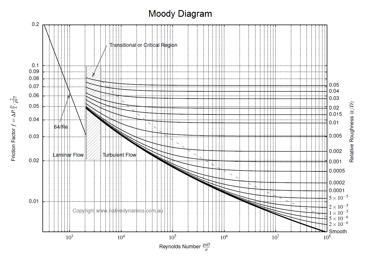
To determine the pressure loss or flow rate through pipe knowledge of the friction between the fluid and the pipe is required. This article describes how to incorporate friction into pressure loss or fluid flow calculations. It also outlines several methods for determining the Darcy friction factor for rough and smooth pipes in both the turbulent and laminar flow regime. Finally this article discusses which correlation for pressure loss in pipe is the most appropriate.
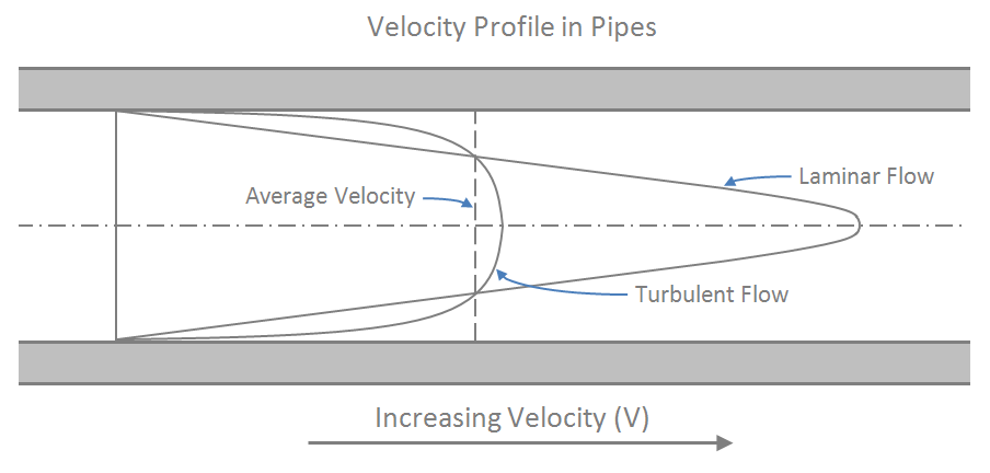
The Reynolds number is dimensionless and describes the ratio of inertial forces to viscous forces in a flowing fluid. It is used in many fluid flow correlations and is used to describe the boundaries of fluid flow regimes (laminar, transitional and turbulent). This article will show you how to calculate and interpret the Reynolds number.
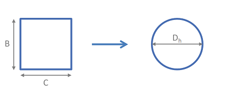
Hydraulic mean diameter provides a method by which non-circular pipe work and ducting may be treated as circular for the purpose of pressure drop and fluid flow rate calculations. This article provides the equations required to determine the hydraulic diameter for a range of non-circular geometries.