Summary
The discharge coefficient is a dimensionless number used to characterise the flow and pressure loss behaviour of nozzles and orifices in fluid systems. Orifices and nozzles are typically used to deliberately reduce pressure, restrict flow or to measure flow rate. This article gives typical values of the discharge coefficient for common orifice and nozzle designs.
Definitions
| : | Discharge Coefficient | |
| : | Discharge Coefficient at infinite Reynolds number | |
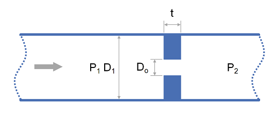
| : | Full pipe diameter | |
| : | Constricted diameter (mm) | |
| : | Resistance Coefficient | |
| : | Reynolds Number (measured at full pipe diameter and velocity) | |
| : | Area Ratio ( ) |
Introduction
There are two distinct uses for nozzles and orifice plates. The first is to restrict flow where high accuracy is generally not important and the second is flow measurement where calculation accuracy is critical.
For the purpose of flow restriction an orifice plate is typically used and it is generally acceptable to use typical values of the discharge coefficient as presented in this article for the orifice sizing calculation.
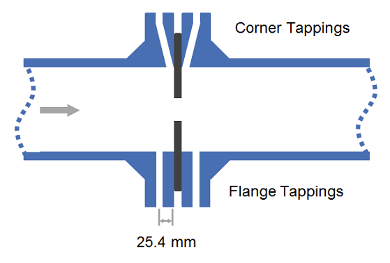
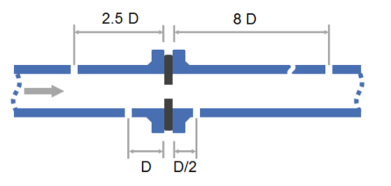
For the purpose of flow measurement either an orifice or nozzle may be used and the accuracy of the discharge coefficient has greater importance. For orifice plate installation the discharge coefficient will vary depending on the location of the pressure tappings. Common arrangements are:
- Corner tappings : Tapping points are at the flange.
- Flange tappings : Tapping points are 1" upstream and downstream of orifice plate in the flanges.
- 2.5D and 8D tappings : Tapping points are 2.5 pipe diameters upstream and 8 pipe diameters downstream.
- D and 1/2 D tappings : Tapping points are 1 pipe diameter upstream and half a pipe diameter downstream.
Other devices with high accuracy and greater pressure recovery exist such as ASME, ISA, Venturi Nozzles and Lo Loss Tubes. When using these devices the vendor should be consulted for the exact discharge coefficient.
Discharge Coefficient Values
Relationship to Resistance coefficient
The discharge coefficient may be directly related to the resistance coefficient via the follow equation:
Typical Values for Discharge Coefficient
For simple pressure loss or flow rate calculations where high accuracy is not critical the following typical values may be used:
| Equipment Type | min | max | |
|---|---|---|---|
| Orifice Plate, thin sharp edged | - | - | 0.61 |
| Venturi Nozzle, Machined | 0.4 | 0.75 | 0.995 |
| Venturi Nozzle, Rough Welded Sheet Metal | 0.4 | 0.70 | 0.985 |
| Venturi Nozzle, Rough Cast | 0.3 | 0.77 | 0.984 |
Precise Relationships for Discharge Coefficient
Where a higher degree of accuracy is required, such as for flow rate measurement, the relationships below may be used.
Values for , and are presented below. Dimensions in millimeters.
| Device | |||
|---|---|---|---|
| Venturi Nozzle, Machined Inlet | |||
| Venturi Nozzle, Cast Inlet | |||
| Venturi Nozzle, Welded Sheet Metal | |||
| Lo-Loss Tube | |||
| Nozzle, ASME Long Radius | |||
| Nozzle, ISA 1932 | |||
| Orifice, Corner Taps | |||
| Orifice, Flange Taps ( ) | |||
| Orifice, Flange Taps ( ) | |||
| and taps | |||
| and taps |
Further Reading
- Flow Measurement Engineering Handbook, R. W. Miller
- Albright's Chemical Engineering Handbook, L. Albright
- Instrument Engineers' Handbook, Vol. 1: Process Measurement and Analysis
Article Tags