Summary
The concept of thermal resistance can be utilised to solve steady state heat transfer problems that involve series, parallel or combined series-parallel components. This article demonstrates how to calculate the total thermal resistance for such systems and how to calculate the thermal resistance for practical geometries such as a pipe wall.
Definitions
| : | Thermal resistance (K/W) | |
| : | Thermal resistance for convective heat transfer (K/W) | |
| : | Thermal resistance for radiative heat transfer (K/W) | |
| : | Thermal resistance for conductive heat transfer through a plane wall (K/W) | |
| : | Heat flow (W) | |
| : | Temperature at a given point (K) | |
| : | Thickness of a plane wall (m) | |
| : | Heat transfer area (m2) | |
| : | Average thermal conductivity (W/m.K) | |
| : | Internal diameter (m) | |
| : | External diameter (m) | |
| : | Length of a pipe (m) | |
| : | Heat transfer coefficient (w/m2.K) |
Introduction
Thermal resistance is the resistance of a particular medium or system to the flow of heat through its boundaries and is dependent upon geometry and thermal properties of the medium such as thermal conductivity.
Accurate knowledge of the thermal resistance for a given system or system component may permit calculation of the heat flow through it or the temperatures on its boundaries. This is of particular use in thermal design problems in industry such as calculating the heat loss from a tank or the selection of piping insulation.
Thermal Resistance Network
Thermal resistance networks are commonly employed in order to analyse steady state heat transfer. Thermal resistance networks have a similar functionality to electrical resistance networks used in electrical engineering and allow for easy calculation of the total thermal resistance in a system whether it is composed of resistances in series, parallel or both.
Resistance in series
Often one must consider heat transfer through various mediums in series, one such example is the heat flow from a gas on one side of a planar wall to the gas on the other side. This heat transfer system may be analysed using the thermal resistance network below.
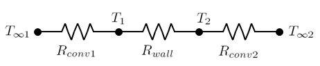
The total resistance for the system described above may be calculated from all the component resistances Rconv1, Rwall and Rconv2 as follows.
Once the total resistance has been calculated the heat flow through the system may be calculated from knowledge of the two end temperatures as follows.
Resistance in parallel
Heat transfer may also occur through resistance in parallel, for example the heat lost from the outer surface of a tank will occur due to both the convective and radiative heat transfer mechanisms.
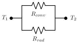
The inverse total resistance for the system shown above may be calculated by adding the inverses resistance of the two components.
This may be simplified so it can be directly combined with the thermal resistances from other components in a given system which is of particular importance when thermal resistances exist in both parallel and series.
Combined series and parallel resistance
In industrial heat transfer problems thermal resistance is often in both series and parallel. For example the heat loss from the contents of an un-insulated tank will have the convective resistance of the tank contents followed by the conductive resistance of the tank walls in series followed by convective and radiative resistance to the surround environment in parallel. This example is described by the thermal resistance network below.
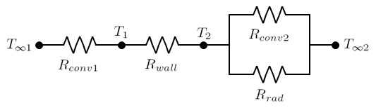
In this instance the total resistance may be calculated by adding the total resistance for the series segment and the total resistance for the parallel segment as described in the previous sections.
Calculation of thermal resistance
In the design and optimisation of industrial equipment it is often required to determine a steady state temperature at some point along a thermal resistance network, for example the temperature between a tank wall and the inside of its insulation.
In order to determine these temperatures one must first calculate the thermal resistances. Some equations for the calculation of thermal resistance are presented below.
Conductive Resistance
Conductive resistance equations for some common cases are outlined in the table below.
| Geometry | Resistance Equation |
|---|---|
| Plane Wall | |
| Cylinder Wall | |
| Spherical Wall |
Convective Resistance
The resistance to heat transfer via convection may be calculated by the following equation.
In order to calculate the convective resistance the heat transfer coefficient, h must first be determined. Many correlations exist to calculate the heat transfer coefficient depending on of the geometry of the system being considered.
Radiative Resistance
The resistance to heat transfer via radiation may be calculated by the following equation:
This allows radiative heat transfer to be easily grouped together with other heat transfer modes when considering total heat transfer for a given system, however the radiative heat transfer coefficient must first be calculated.
Contact Resistance
Typically in heat transfer analysis it is assumed that perfect contact occurs between the surfaces of two components. For this assumption to be correct it would be required that both surfaces be perfectly smooth, however this is rarely the case in practice.
When two real surfaces are pressed together peaks on each surface will contact and form areas of high thermal conductivity while depressions will be occupied by air. As air is a poor thermal conductor this will increase the resistance to heat flow when compared to perfectly smooth surfaces. This increase in resistance is characterised by thermal contact resistance which may be calculated as follows.
Here hc is the thermal contact conductance and is often determined experimentally.
Article Tags