Expansion Coefficient
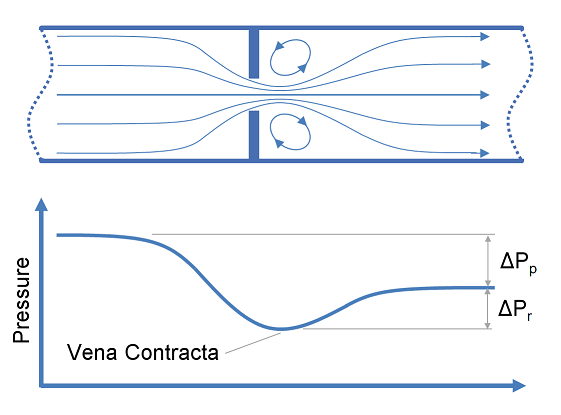
This article provides calculation methods for correlating design, flow rate and pressure loss as a fluid passes through a nozzle or orifice. Nozzles and orifices are often used to deliberately reduce pressure, restrict flow or to measure flow rate.
Definitions
| : | Diameter | |
| : | Area | |
| : | Discharge coefficient | |
| : | Gravitational acceleration | |
| : | Fluid head | |
| : | Change in fluid head | |
| : | Ratio of specific heats ( ) | |
| : | Pressure | |
| : | Differential pressure ( ) | |
| : | Expansion coefficient ( for incompressible flow) | |
| : | Elevation | |
| : | Ratio of pipe diameter to orifice diameter ( ) | |
| : | Mass density |
Subscripts:
For long sections of pipe, the thermal expansion of trapped liquid can be significant. It is often required that the increase in volume of the fluid be determined in order to select suitable thermal relief valves to protect the integrity of the pipework. This article details how to calculate the required relief flow rate to prevent over pressure due to thermal expansion.