Flow Orifice
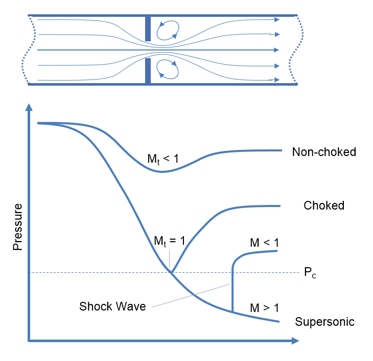
Choked flow is a phenomenon that limits the mass flow rate of a compressible fluid flowing through nozzles, orifices and sudden expansions. Generally speaking it is the mass flux after which a further reduction in downstream pressure will not result in an increase in mass flow rate.
Definitions
| : | Cross sectional area | |
| : | Coefficient of Discharge | |
| : | Mass flux | |
| : | Resistance coefficient | |
| : | Index of polytropic change | |
| : | Mach number | |
| : | Pressure | |
| : | Velocity | |
| : | Mass flow rate | |
| : | Expansion coefficient | |
| : | Ratio of heat capacities, | |
| : | Specific gravity |
Subscripts
| : | Upstream conditions | |
| : | Downstream conditions | |
| : | Choked conditions | |
| : | Throat (minimum flow area) conditions |
Introduction
Non-choked Flow
As a compressible fluid passes through a restriction there are changes in both velocity and pressure. The fluid starts upstream at a higher pressure, which falls as it increases velocity flowing through the restriction, and may continue to fall as the velocity increases through the vena contracta. After passing the vena contracta the fluid will begin expand to fill the cross sectional area of the pipe and as it does will slow down and regain pressure.
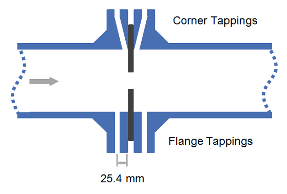
The discharge coefficient is a dimensionless number used to characterise the flow and pressure loss behaviour of nozzles and orifices in fluid systems. Orifices and nozzles are typically used to deliberately reduce pressure, restrict flow or to measure flow rate. This article gives typical values of the discharge coefficient for common orifice and nozzle designs.
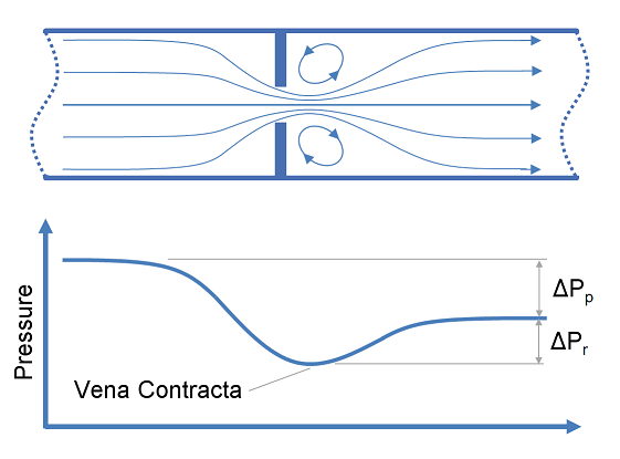
This article provides calculation methods for correlating design, flow rate and pressure loss as a fluid passes through a nozzle or orifice. Nozzles and orifices are often used to deliberately reduce pressure, restrict flow or to measure flow rate.
Definitions
| : | Diameter | |
| : | Area | |
| : | Discharge coefficient | |
| : | Gravitational acceleration | |
| : | Fluid head | |
| : | Change in fluid head | |
| : | Ratio of specific heats ( ) | |
| : | Pressure | |
| : | Differential pressure ( ) | |
| : | Expansion coefficient ( for incompressible flow) | |
| : | Elevation | |
| : | Ratio of pipe diameter to orifice diameter ( ) | |
| : | Mass density |
Subscripts:
Restriction orifices and control valves are commonly used for pressure reduction and measurement of flow rates, however for a liquid system, excessive pressure drop across these items of equipment may result in cavitation. This article describes methods of predicting cavitation across restriction orifices and valves and proposes designs which may be used to avoid cavitation.
Definitions
| : | Cavitation Index (often σ) | |
| : | Upstream Pressure (absolute) | |
| : | Downstream Pressure (absolute) | |
| : | Fluid Vapour Pressure | |
| : | Permanent Pressure Loss | |
| : | Recoverable Pressure Loss |
Introduction
Cavitation occurs in liquid systems and is the result of rapid formation and collapse of vapour bubbles in the liquid. Cavitation must be avoided or controlled as the collapse of vapour bubbles releases significant energy at the location of the bubble collapse. The consequences of this energy release are typically loud noise and pitting damage to contact surfaces, which over time may result in significant damage to or failure of equipment such as pumps or valves.