Fluid Flow

The pressure drop or flow rate through a valve or orifice plate is typically calculated using the a flow coefficient, Cv or orifice diameter. This article demonstrates how to convert between these two parameters when performing functions such as selecting a valve with an equivalent pressure drop to a given orifice plate.
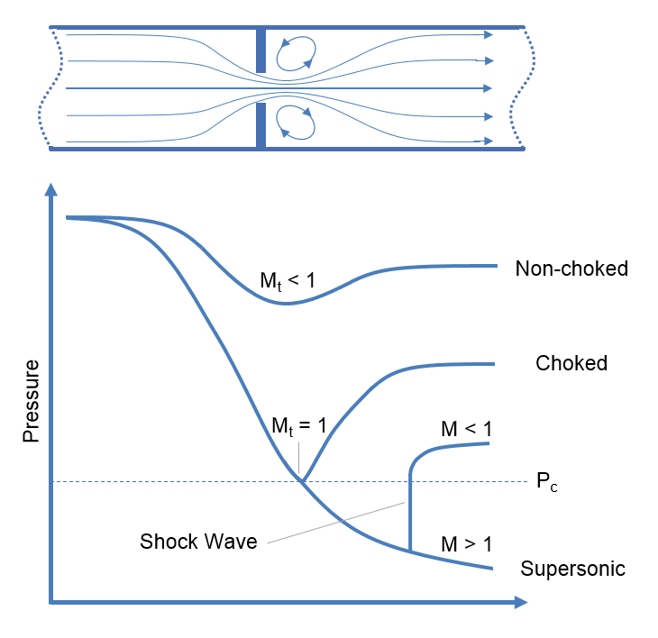
Choked flow is a phenomenon that limits the mass flow rate of a compressible fluid flowing through nozzles, orifices and sudden expansions. Generally speaking it is the mass flux after which a further reduction in downstream pressure will not result in an increase in mass flow rate.
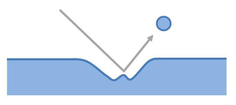
The flow of a gas-liquid multiphase system may cause erosion if velocities are high. This article presents an empirical relationship for estimating whether erosion will occur in a system at a certain velocity.
The Joukowsky equation is a method of determining the surge pressures that will be experienced in a fluid piping system. When a fluid in motion is forced to either stop or change direction suddenly a pressure wave will be generated and propagated through the fluid. This pressure wave is commonly referred to as fluid hammer (also known as water hammer, surge or hydraulic shock) and typically occurs in piping systems when a valve is suddenly closed, isolating the line. The resultant surge pressures are complex to characterise but for simple systems they may be calculated using the Joukowsky equation.
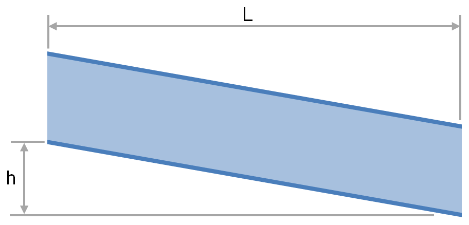
The transport of fluid under gravity is often achieved using partially filled pipes, channels, flumes, ditches and streams. To determine the slope and elevation change required or the flow rate that is achievable one must be able to calculate the head loss and friction factor. This article provides relationships for the calculation of head loss and friction factor for fluids flowing via these conduits.
Standard volumetric flow rates of a fluid are often used to describe the capacity of a vent or pressure relief device. To determine how this capacity compares for another fluid under different pressure and temperature conditions a conversion must be made on the basis of equivalent pressure loss. This article describes the method for calculating the volumetric flow rate of a gas which will give the equivalent pressure drop to another gas through a fixed restriction such as a vent.
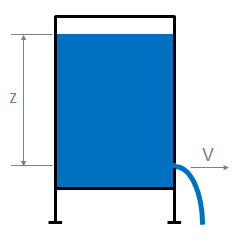
This article presents Torricelli’s law, a simplified method of estimating the velocity of fluid passing through an open orifice under static pressure.
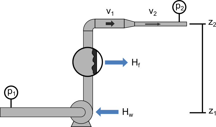
Bernoulli’s Principle is an important observation in fluid dynamics which states that for an inviscid flow, an increase in the velocity of the fluid results in a simultaneous decrease in pressure or a decrease in the fluid’s potential energy. This principle is often represented mathematically in the many forms of Bernoulli’s equation. This article presents some useful forms of Bernoulli’s Equations and their simplifying assumptions.
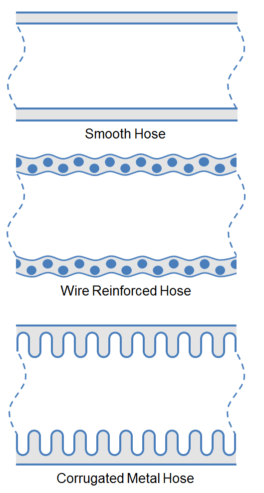
The Pressure loss through a hose is often approximated using coarse heuristics, but utilization of more accurate correlations increase the efficiency of pump and piping designs. This article presents more accurate methods to estimate the pressure loss in various type of hoses using multiples of the pipe length. Methods of estimating pressure loss caused by couplings, curves and coiled hose are also detailed.
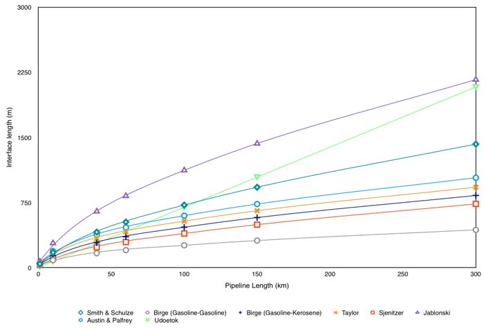
Due to their large capital expense, pipelines are often utilized for the transfer of multiple products. During operation of these multi-product pipelines, the interface between two adjacent products extends (referred to as interface mixing), resulting in the contamination of each product. This interface is typically sent to slops collection for reprocessing or disposal at additional cost to the operator. Therefore the economics of a pipeline can often be improved through a study of product interfaces under various operational conditions to aide in the minimization of interface mixing. This article presents several empirical methods by which interface mixing can be quantified.
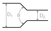
This article provides methods to calculate the K-value (Resistance Coefficient) for determining the pressure loss cause by changes in the area of a fluid flow path. These types of pressure drops are highly dependent on the geometry and are not usually covered in simple pressure loss estimation schemes (such as a single k-value, equivalent length etc.)
Fittings such as elbows, tees, valves and reducers represent a significant component of the pressure loss in most pipe systems. This article details the calculation of pressure losses through pipe fittings and some minor equipment using the 3K method.
Fittings such as elbows, tees, valves and reducers represent a significant component of the pressure loss in most pipe systems. This article details the calculation of pressure losses through pipe fittings and some minor equipment using the 2K method.
Fittings such as elbows, tees, valves and reducers represent a significant component of the pressure loss in most pipe systems. This article details the calculation of pressure losses through pipe fittings and some minor equipment using the K-value method, also known as the Resistance Coefficient, Velocity Head, Excess Head or Crane method.
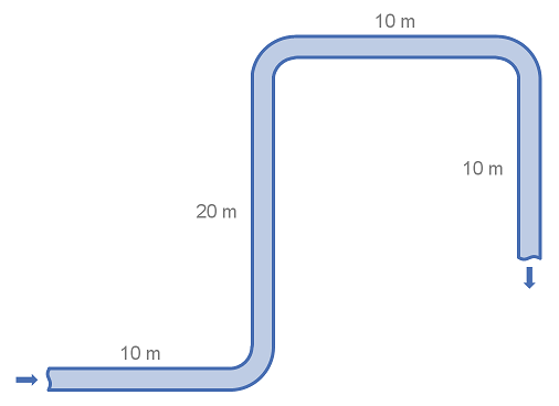
Fittings such as elbows, tees and valves represent a significant component of the pressure loss in most pipe systems. This article details the calculation of pressure losses through pipe fittings and some minor equipment using the equivalent length method. The strength of the equivalent length method is that it is very simple to calculate. The weakness of the equivalent length method is that it is not as accurate as other methods unless very detailed tabulated data is available.
This article describes the method of calculating the velocity head of flowing fluid. The velocity head uses units of length as a measure of the kinetic energy of the flowing fluid.
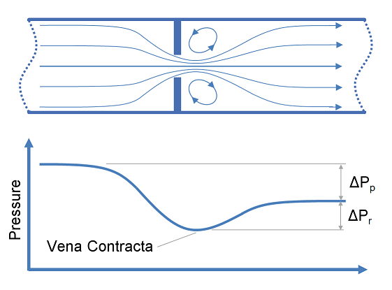
Restriction orifices and control valves are commonly used for pressure reduction and measurement of flow rates, however for a liquid system, excessive pressure drop across these items of equipment may result in cavitation. This article describes methods of predicting cavitation across restriction orifices and valves and proposes designs which may be used to avoid cavitation.
Fittings such as elbows, tees, valves and reducers represent a significant component of the pressure loss in most pipe systems. This article discusses the differences between several popular methods for determining the pressure loss through fittings. The methods discussed for fittings are: the equivalent length method, the K method (velocity head method or resistance coefficient method), the two-K method and the three-K method. In this article we also discuss method for calculating pressure loss through pipe size changes as well as control valves.
Power is consumed by a pump, fan or compressor in order to move and increase the pressure of a fluid. The power requirement of the pump depends on a number of factors including the pump and motor efficiency, the differential pressure and the fluid density, viscosity and flow rate. This article provides relationships to determine the required pump power.
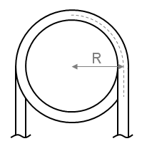
In order to determine the pressure drop in a pipe or coil the friction factor must first be calculated. This article presents the equations which may be used to determine the friction factor in coils and curved pipe.
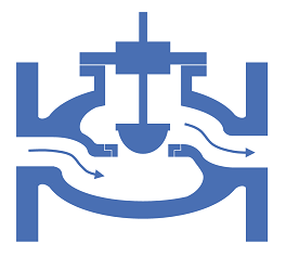
Cv and Kv are singles values in units of flowrate that may be used to characterise the relationship between flowrate and pressure loss for fittings and equipment. This article demonstrates how to calculate the Cv or Kv values, and how to use these values to determine the pressure loss for a given flowrate.
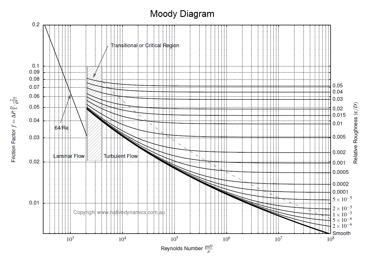
To determine the pressure loss or flow rate through pipe knowledge of the friction between the fluid and the pipe is required. This article describes how to incorporate friction into pressure loss or fluid flow calculations. It also outlines several methods for determining the Darcy friction factor for rough and smooth pipes in both the turbulent and laminar flow regime. Finally this article discusses which correlation for pressure loss in pipe is the most appropriate.
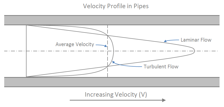
The Reynolds number is dimensionless and describes the ratio of inertial forces to viscous forces in a flowing fluid. It is used in many fluid flow correlations and is used to describe the boundaries of fluid flow regimes (laminar, transitional and turbulent). This article will show you how to calculate and interpret the Reynolds number.
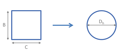
Hydraulic mean diameter provides a method by which non-circular pipe work and ducting may be treated as circular for the purpose of pressure drop and fluid flow rate calculations. This article provides the equations required to determine the hydraulic diameter for a range of non-circular geometries.