Orifice

The pressure drop or flow rate through a valve or orifice plate is typically calculated using the a flow coefficient, Cv or orifice diameter. This article demonstrates how to convert between these two parameters when performing functions such as selecting a valve with an equivalent pressure drop to a given orifice plate.
Definitions
| : | Orifice diameter (m) | |
| : | Flow coefficient, US imperial units | |
| : | Discharge coefficient, dimensionless | |
| : | Ratio of orifice to pipe size , dimensionless |
Subscripts
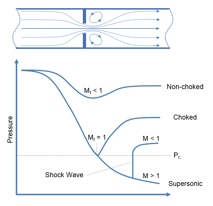
Choked flow is a phenomenon that limits the mass flow rate of a compressible fluid flowing through nozzles, orifices and sudden expansions. Generally speaking it is the mass flux after which a further reduction in downstream pressure will not result in an increase in mass flow rate.
Definitions
| : | Cross sectional area | |
| : | Coefficient of Discharge | |
| : | Mass flux | |
| : | Resistance coefficient | |
| : | Index of polytropic change | |
| : | Mach number | |
| : | Pressure | |
| : | Velocity | |
| : | Mass flow rate | |
| : | Expansion coefficient | |
| : | Ratio of heat capacities, | |
| : | Specific gravity |
Subscripts
| : | Upstream conditions | |
| : | Downstream conditions | |
| : | Choked conditions | |
| : | Throat (minimum flow area) conditions |
Introduction
Non-choked Flow
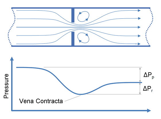
As a compressible fluid passes through a restriction there are changes in both velocity and pressure. The fluid starts upstream at a higher pressure, which falls as it increases velocity flowing through the restriction, and may continue to fall as the velocity increases through the vena contracta. After passing the vena contracta the fluid will begin expand to fill the cross sectional area of the pipe and as it does will slow down and regain pressure.
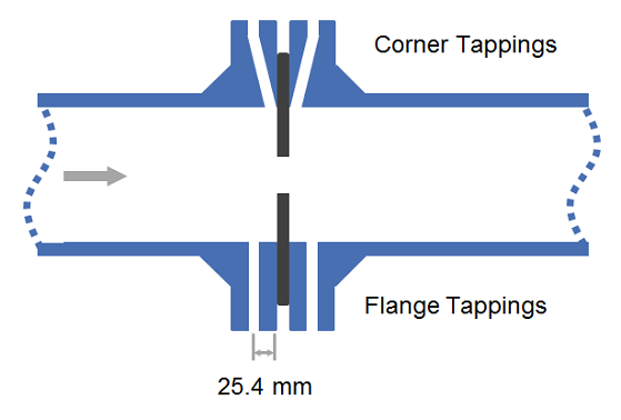
The discharge coefficient is a dimensionless number used to characterise the flow and pressure loss behaviour of nozzles and orifices in fluid systems. Orifices and nozzles are typically used to deliberately reduce pressure, restrict flow or to measure flow rate. This article gives typical values of the discharge coefficient for common orifice and nozzle designs.
This article provides calculation methods for correlating design, flow rate and pressure loss as a fluid passes through a nozzle or orifice. Nozzles and orifices are often used to deliberately reduce pressure, restrict flow or to measure flow rate.
Definitions
| : | Diameter | |
| : | Area | |
| : | Discharge coefficient | |
| : | Gravitational acceleration | |
| : | Fluid head | |
| : | Change in fluid head | |
| : | Ratio of specific heats ( ) | |
| : | Pressure | |
| : | Differential pressure ( ) | |
| : | Expansion coefficient ( for incompressible flow) | |
| : | Elevation | |
| : | Ratio of pipe diameter to orifice diameter ( ) | |
| : | Mass density |
Subscripts:
This article lists the standard effective orifice areas for the orifice designations found in API RP 526 5th edition. These orifice designations set the minimum effective orifice area which a relief valve must have to meet the API 526 requirements and must be used with the sizing equations in API RP 520 Part I.
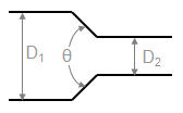
This article provides methods to calculate the K-value (Resistance Coefficient) for determining the pressure loss cause by changes in the area of a fluid flow path. These types of pressure drops are highly dependent on the geometry and are not usually covered in simple pressure loss estimation schemes (such as a single k-value, equivalent length etc.)